
Spherical Roller Bearing Clearance Chart
Sizes in this guide
Spherical Roller Bearing Clearance Chart: the short answer
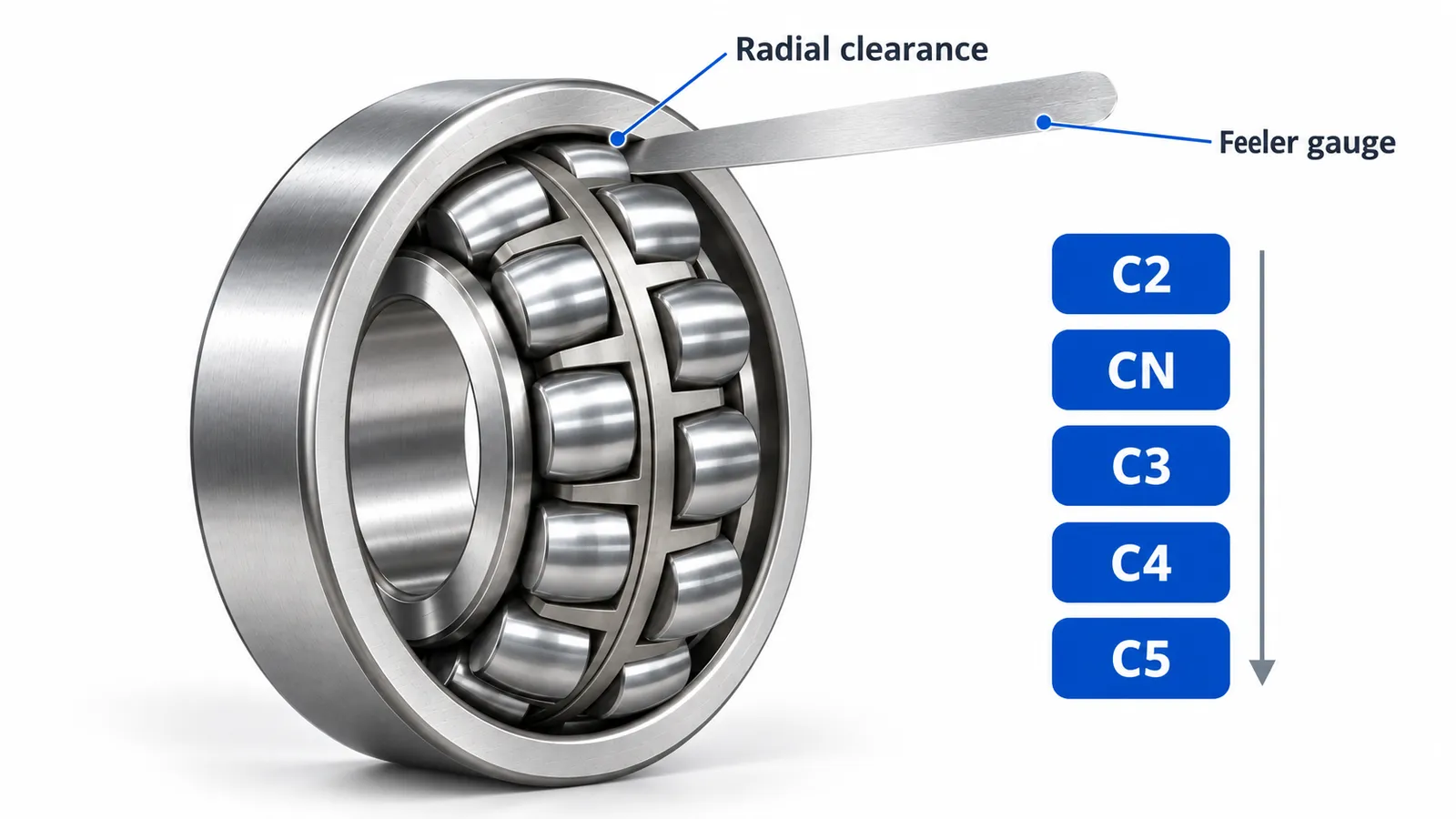
Clearance groups run from smaller to larger: C2, CN (normal), C3, C4, C5. C1 is smaller than C2 and is defined only for some bearing types. C3 is common where the inner ring runs warmer than the outer ring or has a tight fit. For spherical roller bearings the ISO 5753-1 ranges grow with the bore, from about 30–45 µm (CN) at a 40 mm bore to 130–200 µm at a 200 mm bore, and a tapered bore is driven up its sleeve until a set part of that clearance is removed.
Key takeaways
- It depends on bearing size and clearance group. ISO 5753-1 gives the ranges. Operating clearance should stay slightly above zero for most applications.
- Operating clearance is roughly the initial clearance minus the reduction from the interference fit and minus the reduction from the temperature difference between the rings.
- Tapered-bore (K) bearings lose clearance as they are driven up the sleeve; check the residual clearance with feeler gauges.
- C3 is the usual group for sleeve mounting and warm shafts; C4 for vibrating machinery and heavy fits.
What are the radial clearance groups for spherical roller bearings?
Radial internal clearance is the total distance one ring can move relative to the other, measured radially, with no load on the bearing. It is not a defect; it is what the bearing is given at the factory so that after it is pressed onto a shaft and warms up in service it still has a small positive clearance. ISO 5753-1 divides the possible values into groups, from C2 (the tightest) to C5 (the widest), with CN in the middle as the normal group.
| Group | Clearance | Typical use for spherical roller bearings |
|---|---|---|
| C2 | Smaller than normal | Rare; precision applications with light fits and no temperature difference |
| CN | Normal | Shaft fit k6 or m6, ordinary temperatures, cylindrical bore |
| C3 | Larger than normal | The common choice: tapered bore on a sleeve, interference fits, warm shafts, vibrating screens |
| C4 | Larger than C3 | High temperature difference, heavy interference, vibrating machinery, large sizes |
| C5 | Larger than C4 | Extreme temperature difference, very heavy fits |
What are typical radial clearance values by bore?
The values are ranges, not single numbers, and they grow with the bore. The table gives the ISO 5753-1 ranges for spherical roller bearings with a cylindrical bore in the bore sizes ENRO lists most often. Tapered-bore bearings have their own, slightly larger table for the same group, because the taper is expected to reduce the clearance on mounting; it follows below. Use the standard itself, or the bearing maker's catalogue, for bores outside this range.
| Bore d mm (over–incl.) | C2 µm | CN µm | C3 µm | C4 µm | C5 µm |
|---|---|---|---|---|---|
| 30–40 | 15–30 | 30–45 | 45–60 | 60–80 | 80–100 |
| 40–50 | 20–35 | 35–55 | 55–75 | 75–100 | 100–125 |
| 50–65 | 20–40 | 40–65 | 65–90 | 90–120 | 120–150 |
| 65–80 | 30–50 | 50–80 | 80–110 | 110–145 | 145–180 |
| 80–100 | 35–60 | 60–100 | 100–135 | 135–180 | 180–225 |
| 100–120 | 40–75 | 75–120 | 120–160 | 160–210 | 210–260 |
| 120–140 | 50–95 | 95–145 | 145–190 | 190–240 | 240–300 |
| 140–160 | 60–110 | 110–170 | 170–220 | 220–280 | 280–350 |
| 160–180 | 65–120 | 120–180 | 180–240 | 240–310 | 310–390 |
| 180–200 | 70–130 | 130–200 | 200–260 | 260–340 | 340–430 |
Values per ISO 5753-1, as published in manufacturer catalogs. Micrometres, unmounted.
| Bore d mm (over–incl.) | C2 µm | CN µm | C3 µm | C4 µm | C5 µm |
|---|---|---|---|---|---|
| 30–40 | 25–35 | 35–50 | 50–65 | 65–85 | 85–105 |
| 40–50 | 30–45 | 45–60 | 60–80 | 80–100 | 100–130 |
| 50–65 | 40–55 | 55–75 | 75–95 | 95–120 | 120–160 |
| 65–80 | 50–70 | 70–95 | 95–120 | 120–150 | 150–200 |
| 80–100 | 55–80 | 80–110 | 110–140 | 140–180 | 180–230 |
| 100–120 | 65–100 | 100–135 | 135–170 | 170–220 | 220–280 |
| 120–140 | 80–120 | 120–160 | 160–200 | 200–260 | 260–330 |
| 140–160 | 90–130 | 130–180 | 180–230 | 230–300 | 300–380 |
| 160–180 | 100–140 | 140–200 | 200–260 | 260–340 | 340–430 |
| 180–200 | 110–160 | 160–220 | 220–290 | 290–370 | 370–470 |
Values per ISO 5753-1, as published in manufacturer catalogs. Micrometres, unmounted, before driving up the taper.
The related sizes from the ENRO list fall into the rows below. The clearance group available for a given model and quantity is confirmed on the quotation; the ENRO model pages list dimensions and versions, not a clearance value per bearing.
| Model | d × D × B mm | Bore row | CN µm | C3 µm |
|---|---|---|---|---|
| 22210 | 50 × 90 × 23 | 40–50 | 35–55 | 55–75 |
| 22216 | 80 × 140 × 33 | 65–80 | 50–80 | 80–110 |
| 22220 | 100 × 180 × 46 | 80–100 | 60–100 | 100–135 |
| 22312 | 60 × 130 × 46 | 50–65 | 40–65 | 65–90 |
How do you set and measure clearance on a tapered bore?
A K bearing has a 1:12 taper in the bore (1:30 for K30 in the 240 and 241 series). It is mounted on a tapered shaft seat or an adapter sleeve, and driven up the taper until the inner ring has expanded enough to take a set amount of the clearance away. That reduction, not the axial distance, is the real target. You measure it with feeler gauges between the top roller and the outer ring before and after driving up, on a bearing that has been rolled a few turns so the rollers seat.
| Bore d mm (over–incl.) | Reduction in radial clearance mm |
|---|---|
| 30–40 | 0.020–0.025 |
| 40–50 | 0.025–0.030 |
| 50–65 | 0.030–0.040 |
| 65–80 | 0.040–0.050 |
| 80–100 | 0.045–0.060 |
| 100–120 | 0.050–0.070 |
Guide values as published in manufacturer mounting manuals; figures differ slightly between makers. Each maker also publishes the matching axial drive-up distance. Confirm residual clearance with feeler gauges rather than relying on drive-up distance.
Worked example: a 22210 with a tapered bore, group C3, is measured at 0.070 mm before mounting. The 40–50 mm row asks for a reduction of 0.025 to 0.030 mm, so after driving up the feeler gauge should read 0.040 to 0.045 mm. If it reads 0.020 mm the bearing has been driven too far and must be backed off; if it reads 0.060 mm the sleeve has not gripped and the bearing will creep on the shaft. The suffix selector explains when a tapered bore is the right choice.
Which clearance group should you choose?
Start from CN and move up one group for each condition that takes clearance away. An interference fit on the inner ring expands it and takes away a large part of the interference as clearance; a shaft that runs warmer than the housing reduces it further, more so on large bores. A tapered bore on a sleeve reduces it deliberately by the values in the table above. Vibrating screens, crushers and rolls with heavy fits typically run C4, occasionally C5.
| Condition | Effect on clearance | Move to |
|---|---|---|
| Inner ring fit k6 or lighter, housing loose, normal temperature | Little change | CN |
| Inner ring fit m6 or n6, or adapter sleeve mounting | Reduces clearance | C3 |
| Shaft runs noticeably warmer than housing | Reduces clearance | C3, C4 on large bores |
| Vibrating screen, crusher, heavy interference on both rings | Reduces clearance strongly | C4 |
| Both rings interference plus high temperature difference | Reduces clearance strongly | C4 or C5 |
- Operating clearance should stay slightly above zero; a small preload on a spherical roller bearing overheats it fast.
- Do not choose a large group to be safe: too much clearance loads fewer rollers and shortens life.
- Match the group on the replacement to the group on the original unless the original failed by overheating.
How do you order a spherical roller bearing with the right clearance?
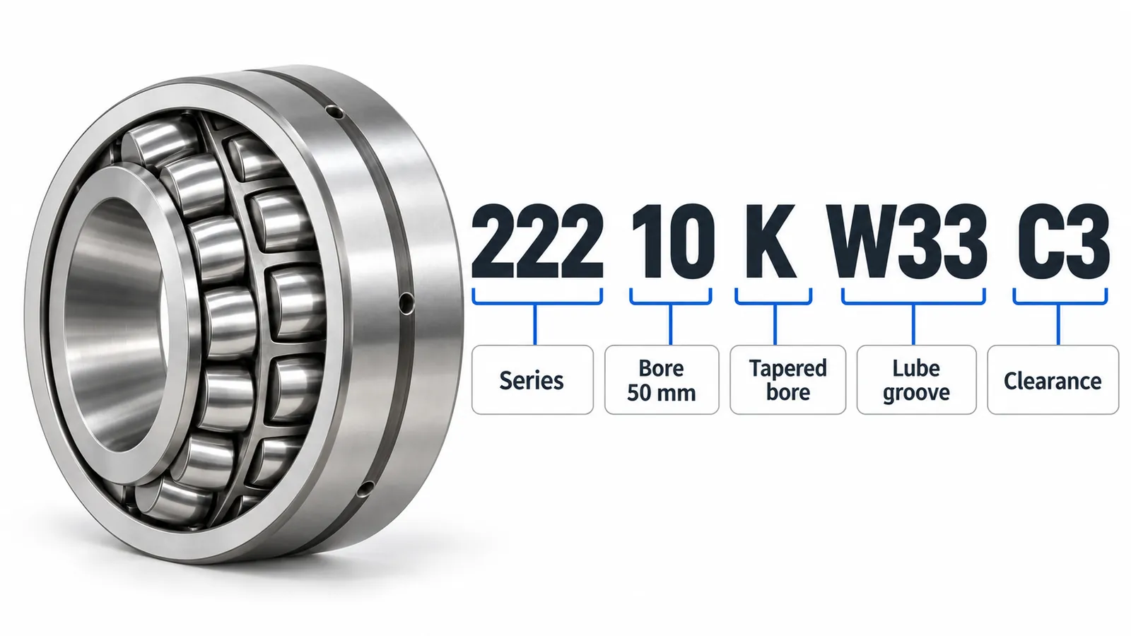
Give the full designation with the clearance suffix, for example 22216 K C3 W33, or state the mounting (cylindrical bore or sleeve) and the duty so we can suggest a group. The spherical roller bearing page lists every size ENRO offers with bore type and W33 groove. Every ENRO bearing is Made in China and passes 100% outgoing inspection under Japan-managed quality control. We reply within 24 hours on business days.
Related ENRO products
Click a model to open its full specification page.